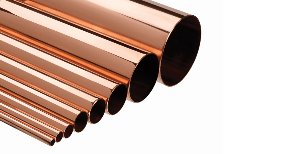
There are two commonly used types of copper tubing, soft (annealed) copper and rigid (cold worked) copper. Copper tube can be used for a wide range of applications, including domestic gas and plumbing, compressed air systems or as refrigerant lines in Heating, Ventilating and Air Conditioning (HVAC) systems.
Copper offers a high level of corrosion resistance and is a malleable, and ductile metal with very high thermal and electrical conductivity. Copper also provides an environmental benefit in that it resists the growth of bacteria, which is an important health consideration for the transportation of water in both commercial and domestic installations.
The value of copper as a global commodity has gone up in recent years, making it prone to possible building site thefts.
Connecting the system:
Copper tube can be joined with a variety of different fitting types typically referred to as traditional “hot working” (soldered or brazed fittings) or using heat free products. Traditional connections comprise capillary fittings, which save material and make smooth, neat, strong and leak-proof joints. Heat free alternatives include compression fittings, grooved, mechanical body grip ring, press-fit and other push-fit type jointing systems.